After the third article, I decided to perform more general work and calculate the same antenna on the different height. In a nutshell, the antenna parameters depend on the height the antenna is placed at. I stored some number of pictures, looking at which worse thousands of words.
The antenna is a quarter-wave GP with two radials. I know that the number of radials does matter, but this is very quick, thus not very thorough exercise. The antenna is made of aluminum pipe (R=10 mm, 3/8 inches), counterpoises are an aluminum wire (R=0.8 mm). The antenna was designed to be mounted on the 1 meter (3 feet) tall mast.
Figure 1. The overall view of the antenna with currents.

Figure 2. The radiation pattern of the antenna 1 meter above the ground. Very nice pattern of the resonant antenna having active resistance about 50 ohms. SWR is 1.1

Figure 3. The SWR plot of the antenna 1 meter above the ground. Surprisingly, the antenna is pretty wideband, the range by SWR 2:1 is 1353 kHz.

The main idea of this exercise is to discover how the placement height affects the antenna.
Figure 4. The radiation pattern of the antenna 3 meters above the ground. One can think this change is too small to be significant. Let's watch the picture: measurement frequency is 14.05 MHz, Z = 40 - j12 (non-resonant with reduced resistance), but the elevation is less by 4 degrees. I haven't change the antenna itself to show you how everything is changed.

Figure 5. The SWR plot of the antenna at 3 meters mast. The resonance has moved to 14.25 MHz, the minimal SWR there is 1.2. The band by SWR 2:1 remains the same: 1353 kHz.

Figure 6. The radiation pattern of the antenna raised to 5 meters above the ground. The pattern now is not as good as before. The resonance is still somewhere, the SWR on 14.05 MHz has raised (1.7 now). But the elevation is being lowered.
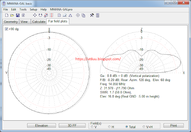
Figure 7. The SWR plot (still 5 meters above the ground). The resonance is still on the 14.25 MHz, but the band becomes narrower, only 1021 kHz.

Let's move further.
Figure 8. The radiation pattern at 10 meters. Now it looks like the butterfly. The characteristics have changed significantly: Z = 32-j5, SWR=1.6, elevation=46 degrees (!!!).

Figure 9. The SWR plot on 10 meters. The antenna now is more wideband: 1724 kHz, but minimal SWR is about 1.5.

Figure 10. The same antenna on the 20 meters mast. The butterfly is much beautiful, the elevation too. The resistance remains the same as it was at 10 meters.

Figure 11. SWR plot. The antenna now is extra-wide: 2700 kHz!

Every ham lowing his amplifier should take care on the antenna. Let's make its characteristics more acceptable for the amplifier. Now the length of wires adapted to make the antenna resonant at 20 meters, the resistance is about 50 Ohms.
Figure 12. The adapted antenna at 20 meters. The radiation pattern remains the same, but the SWR plot differs. Now the antenna is much narrower (only 900 kHz), but its SWR is about 1 on 14.05 and not bigger than 1.5 on the whole 20 meters band.

Increasing the number of counterpoises has brought nothing significant. The elevation angle become 26 degrees, the band has widen a little, the SWR remained intact.
To sum up. Don't think that changes in antenna position won't affect it. Use your VNA to see how your antenna looks at the other end of the coax. At least recalculate the antenna for the given placement height to ensure you have lost nothing.
Комментариев нет:
Отправить комментарий